Structure of Converter
A converter is generally composed of a converter furnace body, supporting mechanism, tilting mechanism, oxygen supply mechanism, etc. For top-blown oxygen converters, bottom-blown converters, and top-bottom combined blown converters, due to different oxygen and gas supply methods, the corresponding equipment structures also vary. The following mainly describes the structure of each part by taking the top-blown oxygen converter as an example.
(一) Converter Furnace Body
The converter furnace body is a large container with a refractory lining inside and a steel plate shell outside. According to the shape of the metal bath, its furnace types can be divided into cylindrical-spherical type, cone-spherical type, and truncated cone type; according to different disassembly methods, there are detachable bottom type and non-detachable bottom type. A reasonable furnace type can adapt to the flow of metal, slag, and furnace gas in the furnace, and is conducive to improving the oxygen supply intensity, reducing splashing, prolonging the furnace life, reducing the loss of furnace lining, and lowering the consumption of refractory materials.
For the cylindrical-spherical converter, its shell is mainly composed of three parts: a conical furnace cap, a cylindrical furnace body, and a spherical furnace bottom. Each part is formed by steel plates and then welded into a whole. The selection of furnace shell materials mainly depends on weldability and creep resistance. At present, carbon steel is generally used, and the service life of the furnace shell will be further prolonged if low-alloy steel plates with good creep resistance are used.
The furnace cap generally adopts a positive mouth furnace cap, that is, a truncated cone with a small upper part and a large lower part, and its inclination angle is generally 60°-68°. The inclination angle should not be too large or too small: if it is too large, slag is easy to flow out from the furnace mouth; if it is too small, the furnace cap is easy to collapse. The furnace mouth should be provided with a reinforcing ring or a box-shaped structure to prevent deformation of the furnace cap.
The inner opening of the tapping hole is located at the connection between the furnace cap and the furnace body. The horizontal inclination angle of the centerline of the tapping hole of a large converter tends to decrease to shorten the length of the tapping hole, thereby shortening the length of the steel flow, reducing heat dissipation and secondary oxidation, and facilitating maintenance.
(二) Supporting Mechanism
The converter supporting mechanism includes a trunnion ring, trunnion, trunnion bearing seat, etc. The trunnion ring is connected to the trunnion and sits on the bearing seat through the trunnion, while the converter sits on the trunnion ring.
The trunnion ring of a small converter is generally of an integral type; that of a large converter is generally of a segmented type, which is then connected into a whole with bolts. The trunnion ring and the furnace shell should be connected safely and reliably, and to prevent damage caused by stress due to the thermal expansion of the furnace shell, they are generally connected with pins or supporting inclined blocks and welded.
The trunnion is usually a hollow shaft (with water cooling inside), which is a transmission part that transmits low-speed, heavy load, and large torque to the converter and trunnion ring. The connection between the trunnion and the trunnion ring has three methods: flange bolt connection, welding, and hot fitting connection.
The trunnion support seat is a component that supports the entire weight of the furnace shell, furnace lining, hot metal (scrap steel), etc. It has a large load, slow rotation speed, high temperature, and extremely harsh working environment. The bearings of the support seat are generally divided into sliding bearings, spherical bearings, and rolling bearings. Rolling bearings are widely used in large and medium-sized converters.
(三) Tilting Mechanism
The tilting mechanism is used to rotate the furnace body and is a key equipment of the converter. Its types include floor-type tilting mechanism, semi-hanging tilting mechanism, hanging tilting mechanism, and hydraulic transmission tilting mechanism. At present, hydraulic transmission tilting mechanisms are widely used in some advanced converters.
(四) Oxygen Supply Mechanism
The oxygen lance is a key component of the oxygen supply mechanism of the converter. The lance body is used for oxygen supply and cooling. The body is composed of three layers of seamless steel pipes set together: the inner layer pipe is for oxygen supply, the space between the inner layer pipe and the middle layer pipe is for water inlet, and the space between the middle layer pipe and the outer layer pipe is for water outlet.
The lance tip is an important part of the oxygen lance. At the beginning, a single-hole Laval-type tip was mostly used, but now multi-hole tips are widely used. Multi-hole tips can be divided into 3-hole Laval-type tips, 3-hole straight-tube-type tips, 4-hole, 6-hole, 7-hole, 8-hole Laval-type tips, and some special-purpose tips.
The oxygen supply mechanism also includes a sub-lance, lance lifting mechanism and replacement device, control valves, measuring instruments, etc.
- Preheating Insulation Material9 个产品
- Bricks15 个产品
- Industry Ceramic Material1 个产品
- Refractory Raw Material11 个产品

Silica Brick
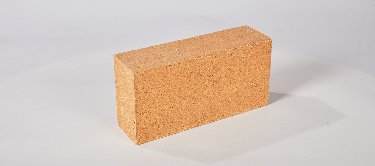
Silica brick is made of quartz containing more than 93% of silicon as the main raw material. It is a firebrick made by high temperature firing. It has strong corrosion resistance to acid slag, high softening degree under load, and does not shrink after refiring. It is mainly used for the partition wall of the carbonization chamber and the combustion chamber of the coke oven, the regenerator chamber of the steel furnace, the soaking furnace, the glass kiln and the ceramic firing kiln, and other supporting parts of the kiln. It is also used for high temperature bearing parts of hot blast furnaces and flat tops of acid furnaces.


